Quick Navigation:
| | | |
Electromagnetism
Hello students! As your Physics teacher, I have prepared this comprehensive, point-wise summary of our complete chapter on Electromagnetism. Read through each section carefully to clear your concepts and prepare for your board exams!
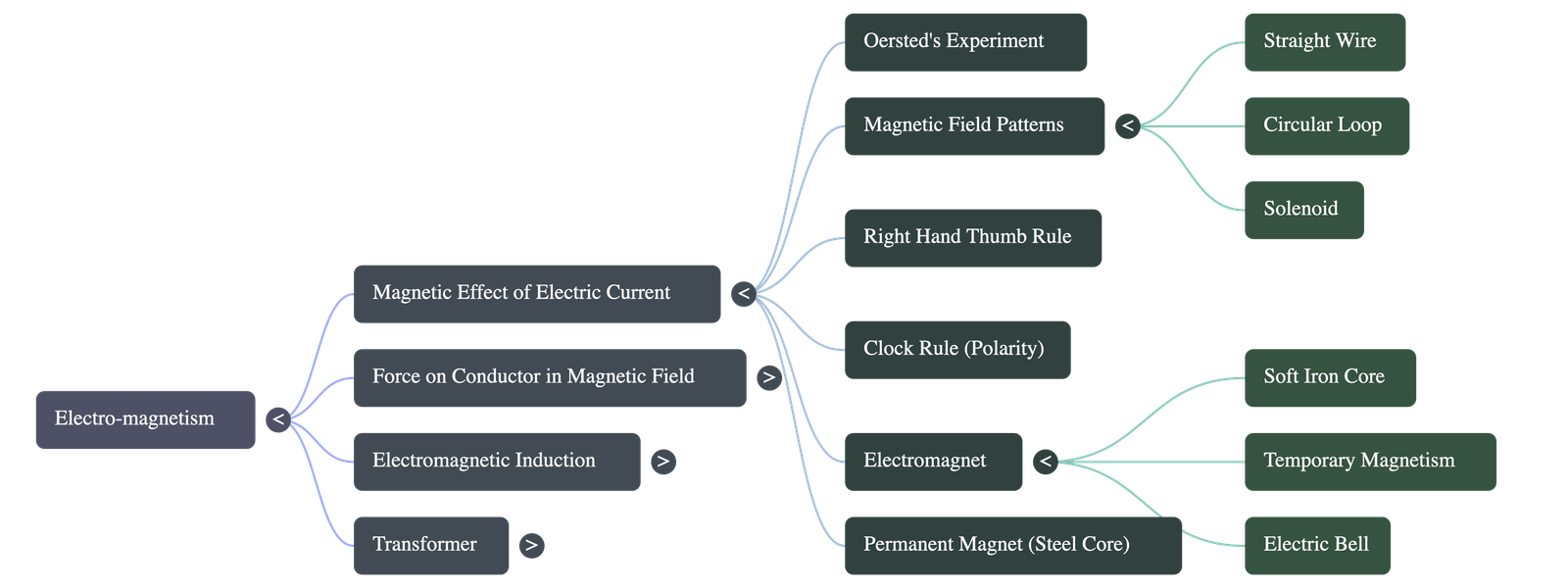
(A) Magnetic Effect of Electric Current
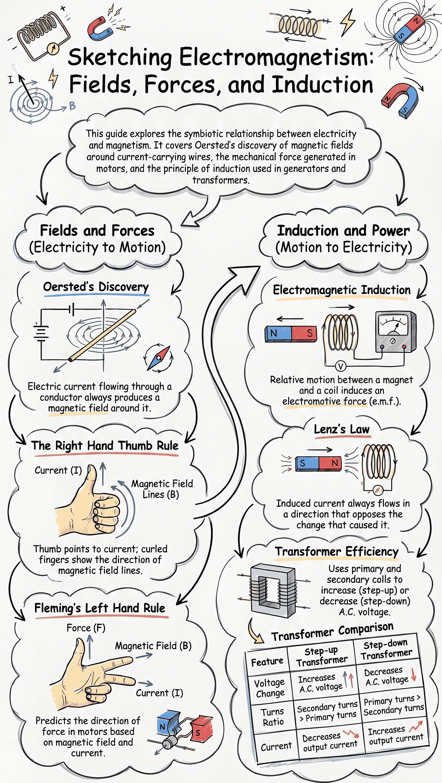
10.1 Oersted's Experiment on the Magnetic Effect of Electric Current
- In 1820, Hans Oersted observed that when an electric current is passed through a conducting wire, a magnetic field is produced around it.
- This field can be detected by placing a magnetic compass needle near the wire; the needle shows deflection when current flows.
- When the direction of the current is reversed, the direction of the deflection in the compass needle also reverses.
- Increasing the current increases the deflection, showing that the magnetic field strength increases.
10.2 Magnetic Field and Field Lines Due to Current in a Straight Wire
- The magnetic field lines around a straight current-carrying wire form concentric circles with the wire as their centre.
- The plane of these circles is perpendicular to the straight wire.
- As you move further away from the wire, the concentric circles become larger and the magnetic field strength decreases.
10.3 Rule to Find the Direction of Magnetic Field
- Right Hand Thumb Rule: If you hold the current-carrying conductor in your right hand such that the thumb points in the direction of the current, then the direction in which your fingers encircle the wire gives the direction of the magnetic field lines.
10.4 Magnetic Field Due to Current in a Loop (or Circular Coil)
- The magnetic field lines near the wire of the loop are nearly circular.
- At the centre of the loop, the field lines are straight, parallel to each other, and perpendicular to the plane of the loop, indicating a uniform magnetic field near the centre.
- Clock Rule: Used to find polarity at the faces of the loop. If the current flows in a clockwise direction on a face, it behaves as a South Pole. If the current flows in an anticlockwise direction, it behaves as a North Pole.
10.5 Magnetic Field Due to a Current Carrying Cylindrical Coil (Solenoid)
- A solenoid is a long cylindrical coil of insulated copper wire. When current is passed through it, it behaves exactly like a bar magnet.
- The magnetic field lines inside the solenoid are nearly straight and parallel, meaning the magnetic field is uniform inside.
- The field strength can be increased by: increasing the current, increasing the number of turns, or placing a soft iron core along its axis.
10.6 Electromagnet
- An electromagnet is a temporary strong magnet made by passing current in a coil wound around a piece of soft iron.
- It loses its magnetism as soon as the current is switched off.
- They are commonly made in two shapes: I-shape (bar) and U-shape (horseshoe). U-shape magnets produce a very strong magnetic field in the gap between the two poles.
10.7 Permanent Magnet
- Made by winding a coil over a piece of steel (instead of soft iron) and passing a current.
- Steel has high magnetic retentivity, meaning once magnetized, it does not easily lose its magnetism even after the current is switched off.
- Used in devices like galvanometers, ammeters, voltmeters, and magnetic compasses.
10.8 & 10.9 Comparison and Advantages of Electromagnet over Permanent Magnet
- An electromagnet is made of soft iron, whereas a permanent magnet is made of steel.
- An electromagnet can produce a much stronger magnetic field than a permanent magnet.
- The strength of an electromagnet can easily be changed (by changing current or turns), while a permanent magnet's strength is fixed.
- The polarity of an electromagnet can be reversed by reversing the current, which cannot be done with a permanent magnet.
- An electromagnet can easily be demagnetized by switching off the current.
10.10 Uses of Electromagnet
- Lifting and transporting heavy iron scrap (can lift up to 20,000 kg).
- Separating iron pieces from non-magnetic debris or ores.
- Removing iron splinters from wounds in hospitals.
- Major component in devices like the electric bell, telegraph, tram, motor, and relay.
- Electric Bell Working: When the switch is pressed, current flows, the electromagnet attracts the soft iron armature, causing the hammer to strike the gong. This movement breaks the circuit at the contact screw. The electromagnet loses magnetism, the spring pulls the armature back, remaking the circuit. This "make and break" repeats rapidly, ringing the bell continuously.
(B) Force on a Current Carrying Conductor in a Magnetic Field & D.C. Motor
10.11 Force on a Current Carrying Conductor (Lorentz Force)
- A current-carrying conductor placed in a magnetic field experiences a mechanical force.
- The magnitude of the force (F) depends on the current (I), the magnetic field strength (B), and the length of the conductor (l). Formula: F = IBl (when perpendicular).
- No force acts on the wire if it is placed parallel to the magnetic field.
- Fleming’s Left Hand Rule: Stretch the thumb, forefinger, and central finger of your left hand mutually perpendicular. Forefinger = Field direction, Central finger = Current direction, then Thumb points to the direction of Force (or motion).
10.12 Simple D.C. Motor
- Principle: Converts electrical energy into mechanical energy. It works on the principle that a current-carrying coil placed in a magnetic field experiences a torque (turning effect) which rotates it.
- Main Parts:
- Armature: A rectangular copper coil wound on a soft iron core.
- Strong Magnet: A horseshoe magnet providing a strong magnetic field.
- Split Ring Commutator: Two halves of a copper ring. It reverses the direction of current in the coil after every half rotation, ensuring the coil keeps rotating in the same direction.
- Carbon Brushes: Gently press against the split rings to supply direct current from the battery to the rotating coil without tangling wires.
- The speed of rotation can be increased by: increasing the current, increasing the number of turns in the coil, increasing the area of the coil, or increasing the strength of the magnetic field (e.g., by using a soft iron core).
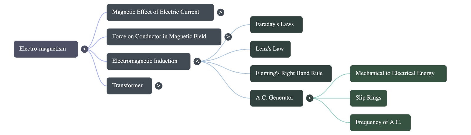
(C) Electromagnetic Induction, A.C. Generator and Transformer
10.13 & 10.14 Electromagnetic Induction & Faraday's Laws
- Electromagnetic Induction (EMI): Discovered by Michael Faraday. It is the phenomenon of producing an induced e.m.f. (and hence an induced current) in a closed coil due to a change in the magnetic flux linked with it.
- Whenever there is a relative motion between a coil and a magnet, an electromotive force (e.m.f.) is induced.
- Faraday’s Laws:
- Whenever the magnetic flux linked with a coil changes, an e.m.f. is induced. It lasts as long as the change continues.
- The magnitude of the induced e.m.f. is directly proportional to the rate of change of magnetic flux linked with the coil.
- Lenz's Law: The direction of the induced e.m.f. (or current) is always such that it opposes the cause (change in magnetic flux or relative motion) which produces it. This law is based on the conservation of energy.
- Fleming’s Right Hand Rule: Used to find the direction of induced current. Stretch thumb, forefinger, and central finger of right hand mutually perpendicular. Thumb = Motion of conductor, Forefinger = Magnetic Field, Central finger indicates direction of Induced Current.
10.15 A.C. Generator
- Principle: Converts mechanical energy into electrical energy based on the principle of electromagnetic induction.
- Construction: Similar to a D.C. motor but instead of split rings, it uses two separate coaxial slip rings (S1 and S2) that rotate completely with the coil. Carbon brushes press against these slip rings.
- Working: As the armature coil rotates in the magnetic field, the magnetic flux linked with it changes continuously, inducing an alternating e.m.f. The current reverses its direction every half rotation, creating an Alternating Current (A.C.).
10.16 Frequency of A.C. in Household Supplies
- In India, house electricity is supplied at a frequency of 50 Hz. This means the alternating current reverses its direction 100 times in a single second.
- Difference between A.C. and D.C.: Direct Current (D.C.) always flows in one direction with constant magnitude. Alternating Current (A.C.) continuously changes magnitude and reverses direction periodically.
- A.C. is advantageous over D.C. because it can be transmitted over long distances using transformers with minimal energy loss.
10.17 Distinction Between A.C. Generator and D.C. Motor
- Generator: Converts mechanical to electrical energy, works on electromagnetic induction, and uses slip rings.
- Motor: Converts electrical to mechanical energy, works on the principle of force on a current-carrying conductor in a magnetic field, and uses a split ring commutator.
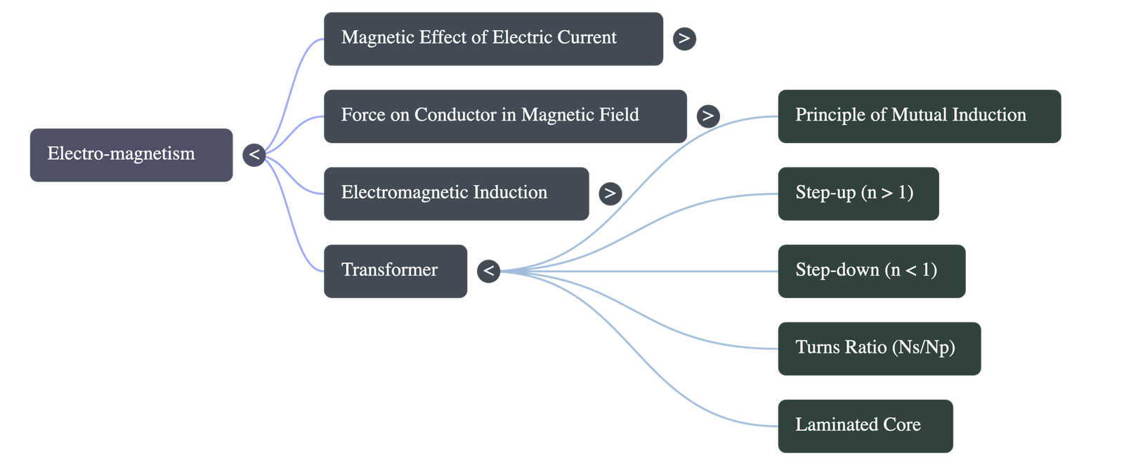
10.18 Transformer
- Principle: A device used to increase or decrease the magnitude of alternating voltage. It works on the principle of electromagnetic induction across two coils.
- Construction: Consists of a Primary coil (input) and a Secondary coil (output) wound around a laminated soft iron core. Note: A transformer does NOT work on direct current (D.C.).
- Types:
- Step-up Transformer: Increases AC voltage, decreases current. Secondary turns > Primary turns. Secondary wire is thinner. Used at power generating stations.
- Step-down Transformer: Decreases AC voltage, increases current. Primary turns > Secondary turns. Secondary wire is thicker (to handle higher current). Used at city sub-stations.
- Turns Ratio (n): Ratio of number of turns in secondary coil to primary coil (n = Ns / Np). For ideal transformers: Power input = Power output.
- Energy Losses:
- Eddy currents: Minimized by using a laminated iron core instead of a solid block.
- Copper loss (Heat): Minimized by using thicker wires where the current is high.
- Hysteresis loss: Minimized by using soft iron for the core.
Teacher's Note:
Make sure you are completely clear on the differences between the Right Hand Thumb Rule, Fleming's Left Hand Rule, and Fleming's Right Hand Rule. They are frequently asked in exams! Best of luck with your revision!
Do checkout all questions & answers of this chapter.
Quick Navigation:
| | | |
1 / 1
Quick Navigation:
| | | |