Quick Navigation:
| | | |
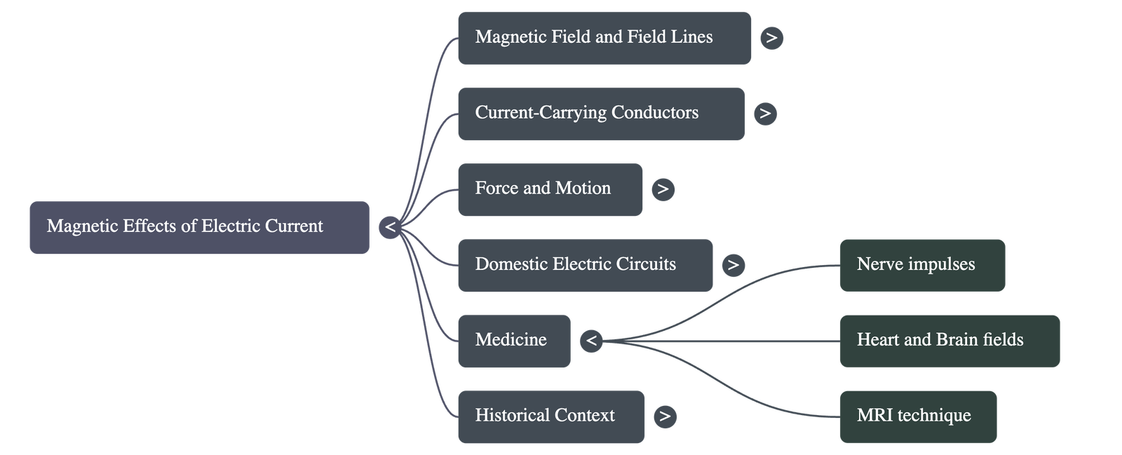
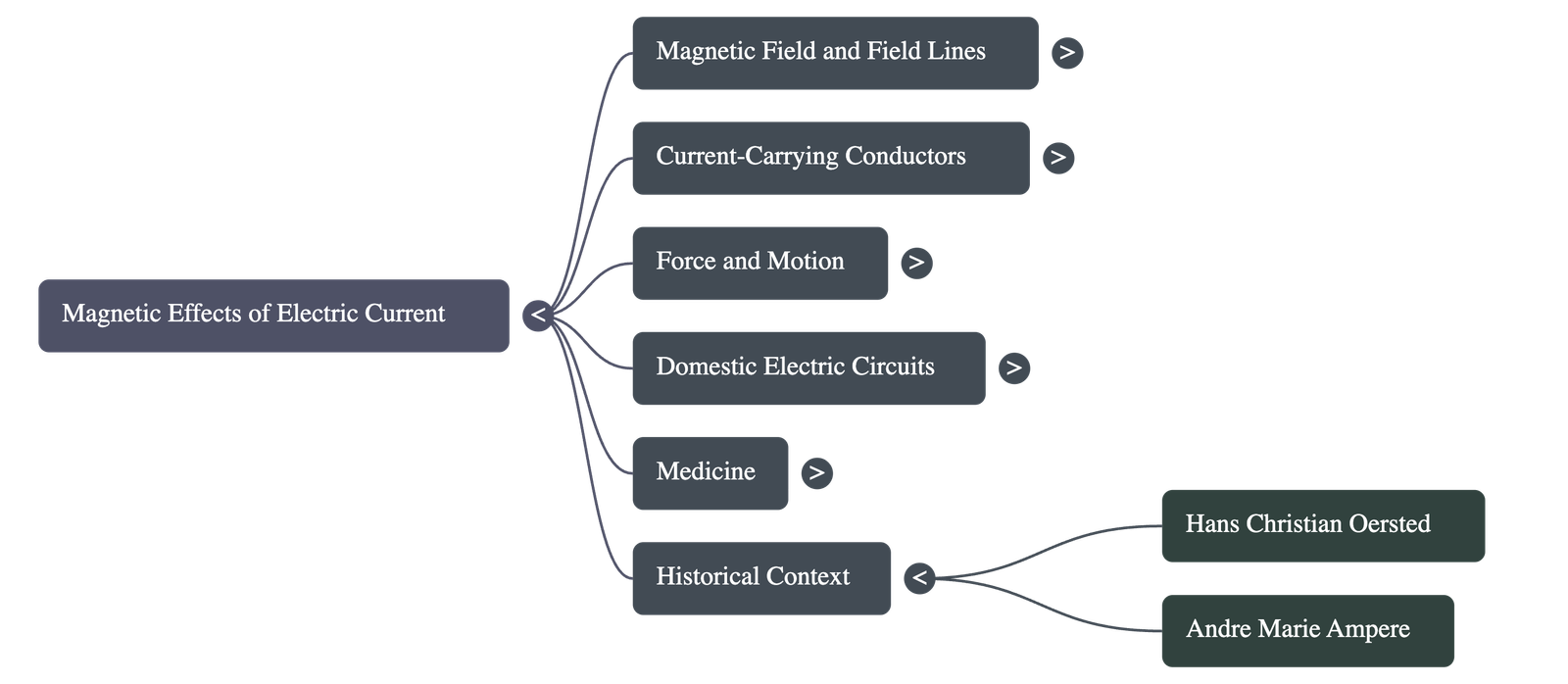
Magnetic Effects of Electric Current
1. Introduction to Electromagnetism
- Discovery: Hans Christian Oersted (1820) discovered that a compass needle gets deflected when placed near a wire carrying an electric current.
- Significance: This observation established that electricity and magnetism are related phenomena; an electric current produces a magnetic effect.
2. Magnetic Field and Field Lines
- Magnetic Field: The region surrounding a magnet where its force can be detected. It is a quantity that possesses both magnitude and direction.
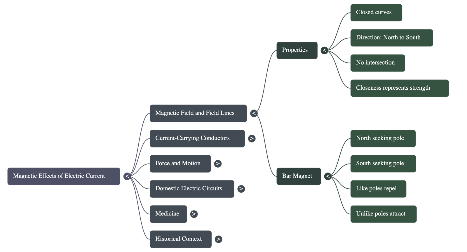
- Compass Needle: It acts as a small bar magnet. The end pointing north is the North Pole, and the end pointing south is the South Pole. Like poles repel, while unlike poles attract.
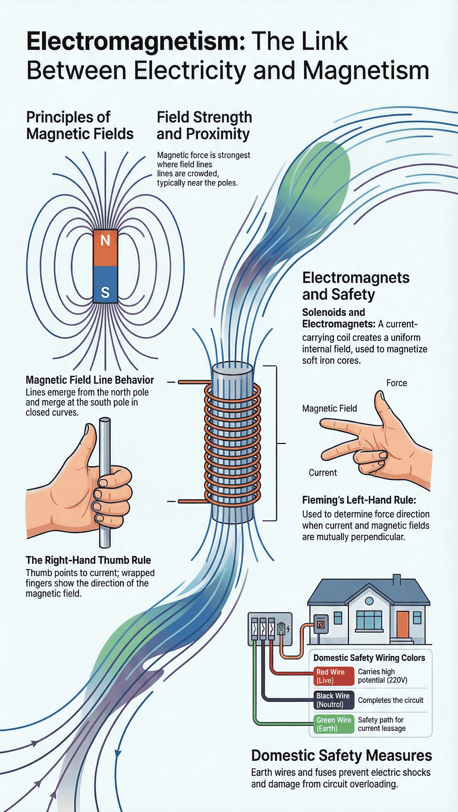
- Properties of Magnetic Field Lines:
- Direction (Outside Magnet): Field lines emerge from the North Pole and merge at the South Pole.
- Direction (Inside Magnet): Field lines move from the South Pole to the North Pole.
- Closed Curves: Magnetic field lines form continuous closed loops.
- Field Strength: Represented by the closeness of the lines. The field is stronger where lines are crowded (near the poles).
- No Intersection: No two field lines can cross each other. If they did, it would imply two different directions of the magnetic field at a single point, which is impossible.
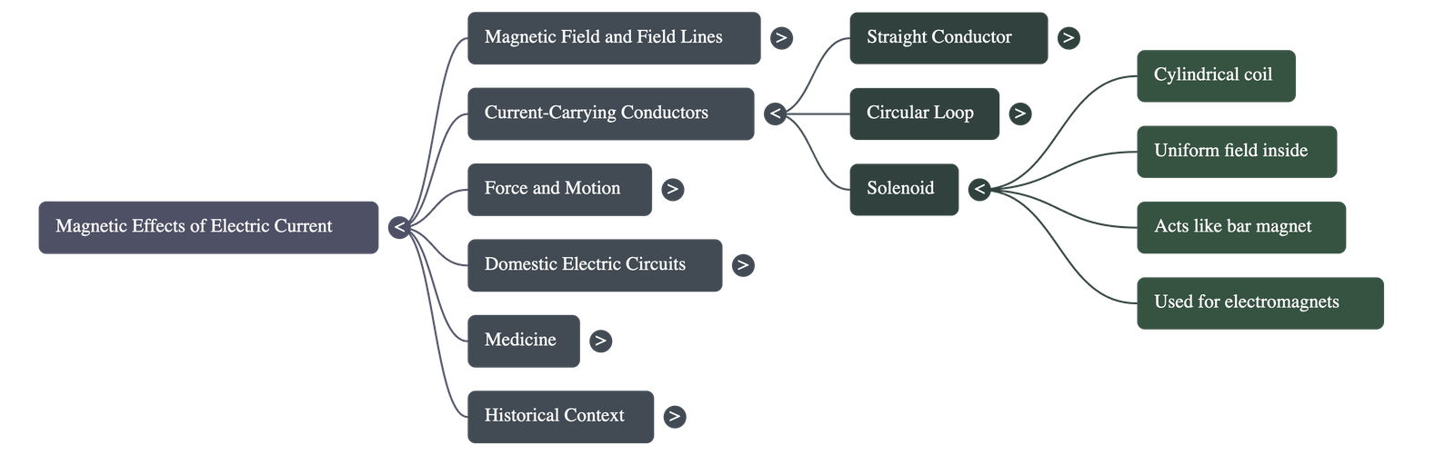
3. Magnetic Field due to Current-Carrying Conductors
The pattern of the magnetic field depends on the shape of the conductor.
A. Straight Conductor
- Pattern: The magnetic field lines form concentric circles around the wire.
- Factors Affecting Strength:
- Directly proportional to the current flowing through the wire.
- Inversely proportional to the distance from the wire (circles get larger as we move away).
- Right-Hand Thumb Rule: A rule to find the direction of the magnetic field. If you hold a current-carrying straight conductor in your right hand with the thumb pointing in the direction of the current, your fingers will wrap around the conductor in the direction of the magnetic field lines.
B. Circular Loop
- Pattern: The concentric circles become larger as we move away from the wire. At the center of the loop, the arcs appear as straight lines.
- Additive Nature: Every section of the wire contributes to the magnetic field lines in the same direction within the loop.
- Multiple Turns: If a coil has n turns, the field produced is n times stronger than a single turn because the current in each turn flows in the same direction.
C. Solenoid
- Definition: A coil of many circular turns of insulated copper wire wrapped closely in the shape of a cylinder.
- Field Pattern: Similar to that of a bar magnet. One end acts as the North Pole and the other as the South Pole.
- Field Inside: The field lines inside the solenoid are parallel straight lines, indicating a uniform magnetic field at all points inside.
- Electromagnet: A strong magnetic field inside a solenoid can be used to magnetize a magnetic material (like soft iron) placed inside it. The magnet formed is called an electromagnet.
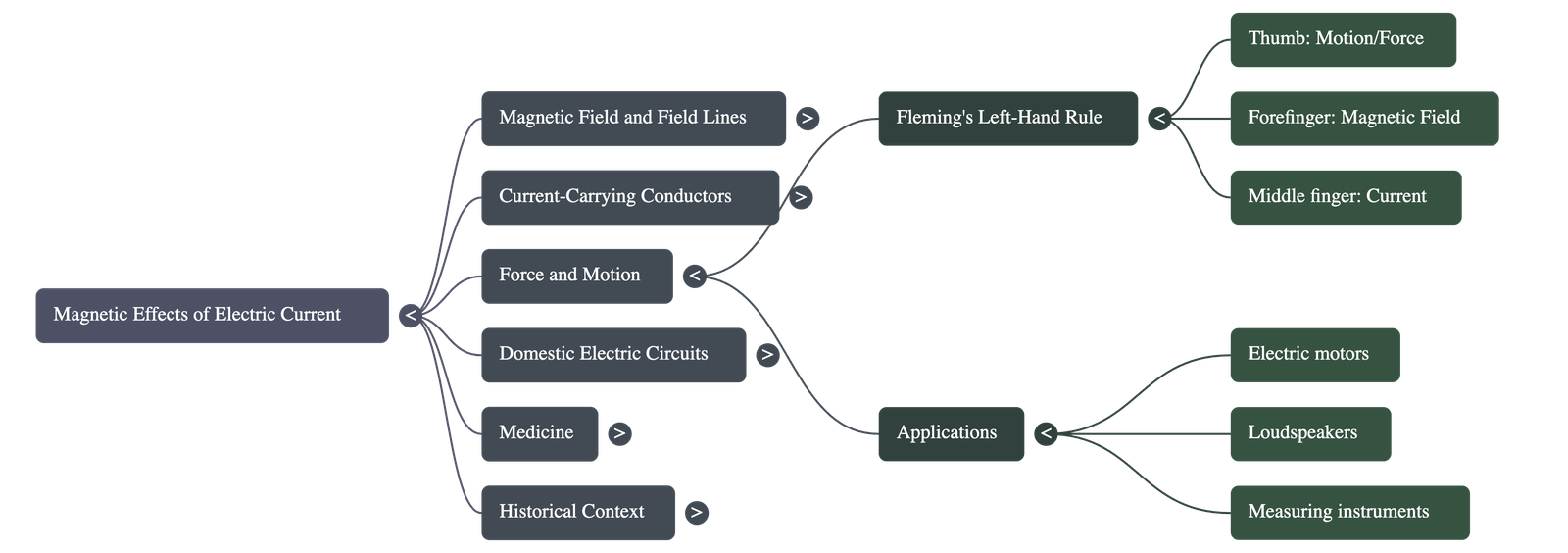
4. Force on a Current-Carrying Conductor
- Principle: A current-carrying conductor placed in a magnetic field experiences a mechanical force. Ideally, the magnet exerts an equal and opposite force on the conductor.
- Factors Affecting Force:
- The direction of the force is reversed if the direction of the current is reversed.
- The direction of the force is reversed if the direction of the magnetic field is reversed.
- The displacement (force) is largest when the direction of the current is at right angles to the direction of the magnetic field.
- Fleming’s Left-Hand Rule: Used to find the direction of the force/motion. Stretch the thumb, forefinger, and middle finger of the left hand mutually perpendicular to each other:
- Forefinger: Points in the direction of the Magnetic Field.
- Middle finger: Points in the direction of the Current.
- Thumb: Points in the direction of Motion (Force).
- Applications: This principle is used in electric motors, generators, loudspeakers, and microphones.
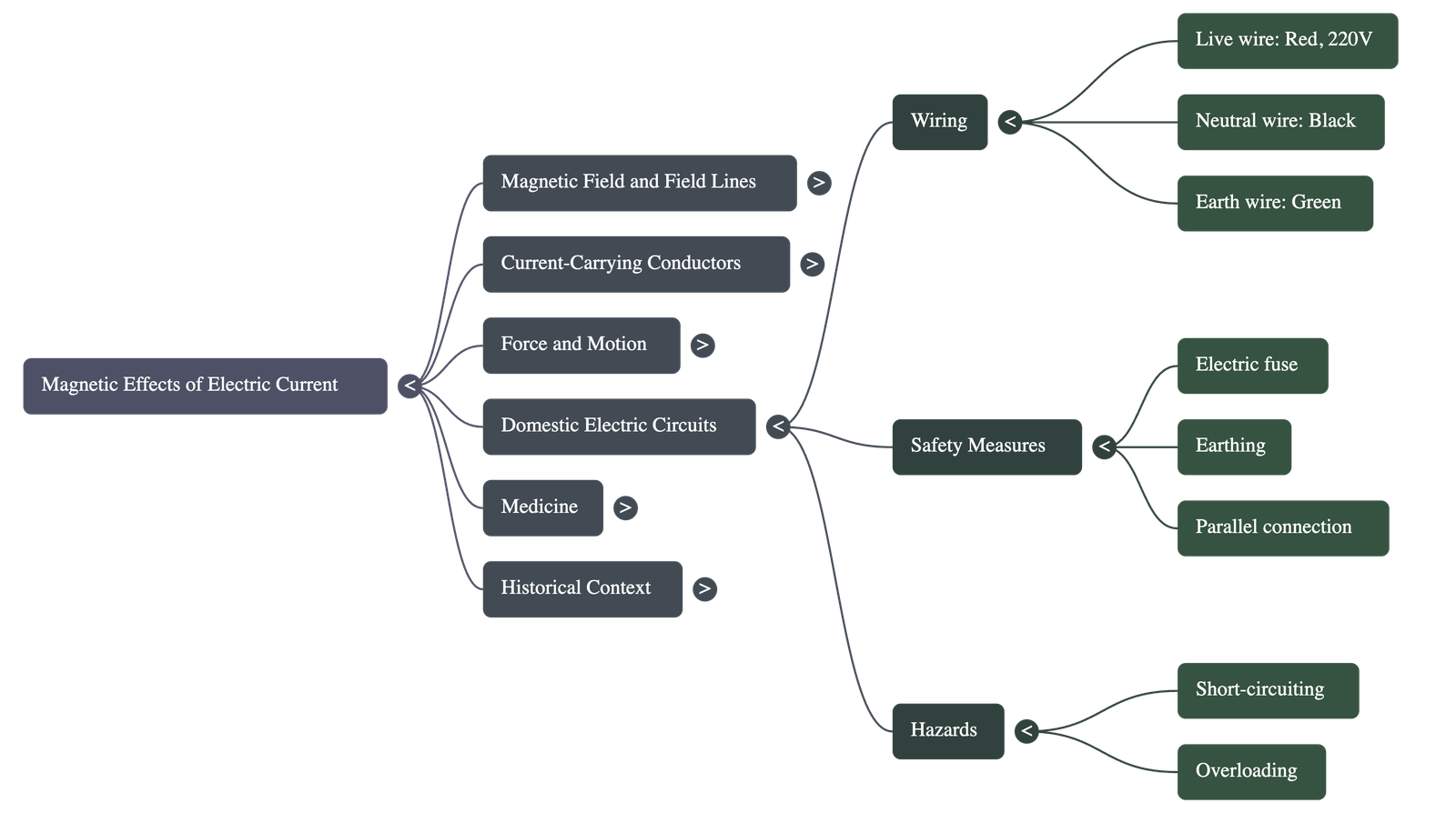
5. Domestic Electric Circuits
- Power Supply: Received via the "mains" with a potential difference of 220 V.
- Live Wire (Red insulation): Positive wire.
- Neutral Wire (Black insulation): Negative wire.
- Earth Wire (Green insulation): A safety measure connected to a metal plate deep in the earth. It is connected to the metallic body of appliances to provide a low-resistance path for leakage current, preventing electric shock.
- Circuit Arrangements:
- Appliances are connected in parallel so that each has an equal potential difference and a separate switch.
- Separate circuits are often used for high-power ratings (15 A for geysers, etc.) and low-power ratings (5 A for bulbs, fans, etc.).
- Electric Fuse: An important safety device placed in series.
- Function: Stops the flow of unduly high current by melting (due to Joule heating) and breaking the circuit.
- Purpose: Prevents damage to appliances and circuits during overloading or short-circuiting.
- Short-Circuiting: Occurs when the live wire and neutral wire come into direct contact, causing current to increase abruptly.
- Overloading: Caused by connecting too many appliances to a single socket or an accidental hike in supply voltage.
Quick Navigation:
| | | |
1 / 1
Quick Navigation:
| | | |